- 12.1 Engine arrival
- 12.1 Engine Installation Prep
- 12.1 Engine Installation Prep
- 12.1.2 Engine Mounts
- 12.1.2 Engine Installation
- 12.2.1 Aluminun Oil Lines
- 12.2.1 Aluminum Oil Lines
- 12.2.1 Cabin Heat
- 12.2.2 Fuel Lines
- 12.2.2 Fuel Lines
- 12.1.2 Intake tube modification
- 12.2.2 Fuel Lines
- 12.1.2 Intake tube modification
- 12.1.2 Intake tube modification (completed)
- 12.3.1 – Installing Throttle, Mixture, and Prop Controls
- 12.3.1 – Mixture Control Mounting Bracket
- 12.3.1 Prop Control Bracket
- 12.3.1 Throttle Control Bracket
- 12.2.3 Cylinder Intake Drain Lines
- 12.2.1 – Aluminum Oil Lines
- 12.3.4 Cooling Plenum
- 12.1.2 Oil Cooler mod
- 12.2.4 Pressure lines
- 12.3.4 Cooling Plenum
- 12.2.4 Pressure Lines
- 12.3.4 Cooling Plenum Intakes
- 12.2.3 Electric Fuel Pump Drain
- 12.2.3 Mechanical Fuel Pump Drain
- 12.2.3 Fuel Pump Drain Lines
- 12.2.3 Spider Drain Line
- 12.3.5 Propeller
- 12.4 Exhaust Installation
- 12.3.6 Nose Oil Cooler
- 12.3.6 Nose Oil Cooler Control
- 12.4 EGT Probe Installation
- 12.2.4 Oil Pressure Sensor (remediation)
- 12.4 Oil breather line
- 12.3.4 NACA duct extensions
- 12.4.2 Exhaust Fairing
- 12.3.6 Cabin Heat Damper Control
- 12.99 Induction Air
- 12.2.2 Fuel Line
- 12.3.6 Nose Mounted Oil Cooler
- 12.99 Engine Woes
- Engine Dehydrator
- Fouled injectors
- 12.99 – Oil temperature and heat challenges
- 12.99 Cabin Heat
- Electronic Ignition
- 12.99 Engine induction air
Time to make an engineering change. The oil is cooled with two oil coolers. The primary oil cooler is in the back with the engine. There’s a secondary oil cooler in the nose that’s used to cool engine oil and provide cabin heat. A NACA duct is installed in the side of the nose, the oil cooler is mounted and another duct exits the bottom. Two 1 1/2″ tubes are inserted into the exit duct that supply warm(er) air to the cabin area. A small flap/diverter is installed in after the tubes that would block the air from exiting outside and instead directs it to the cabin. Here’s the problem: At cruise speed, the air is forced through the oil cooler at an incredible rate. And in the winter, the air at cruise altitude can 20 – 30 below zero. Given that, I think the oil cooler would increase the temperature of the outside air maybe 50 degrees. Which means that the cabin would be “heated” with 30 – 40 degree air.
So here’s the plan: I’ll put an additional flap between the NACA duct and the oil cooler to block the outside air. Then run a return line from the cabin to the oil cooler. That way I’ll be heating inside air that already warm.
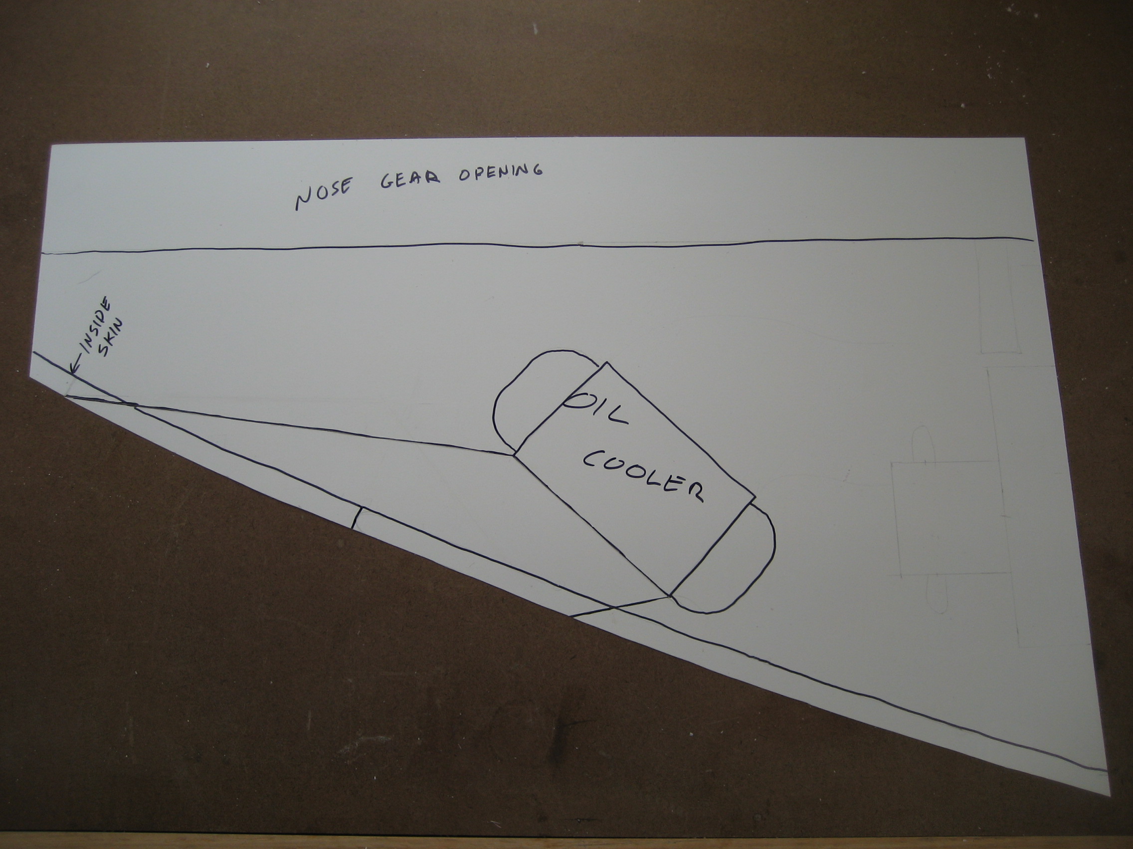
This plan requires fabricating almost all the parts. Here’s the plan view. On paper.
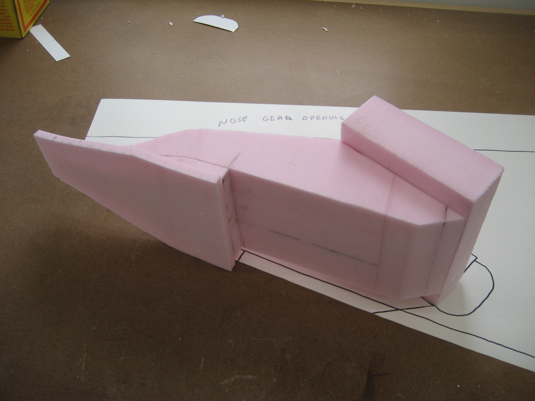
I’ll make a form out of foam and cover it with fiberglass. I used a spreadsheet based the formula for the NACA design developed by the NASA predecessor in the 1950’s.
Here’s the form made from glued blocks of foam.
This is the result. Needs a little cleanup but not bad.

Test fit to see if it’s going to work.
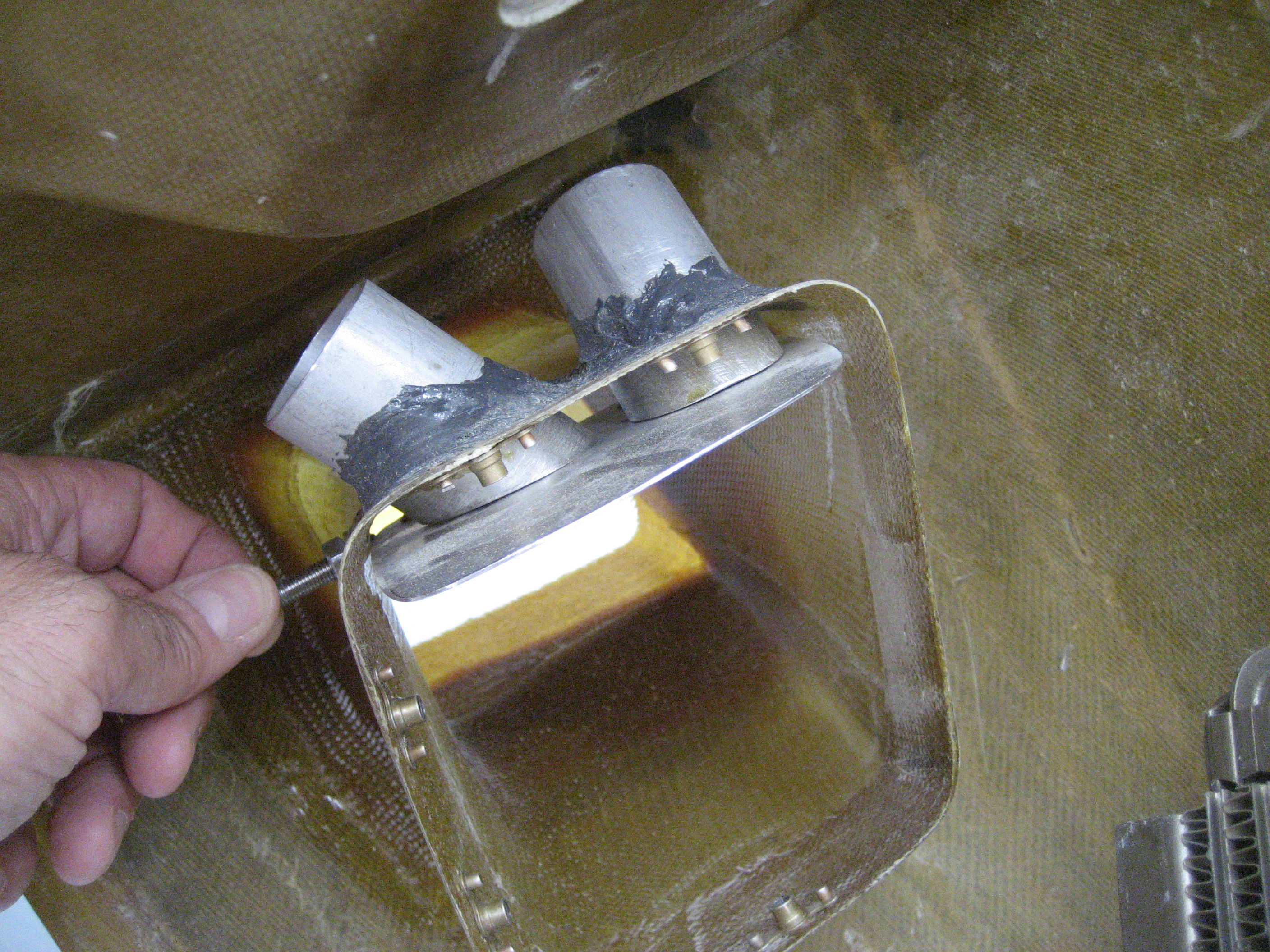
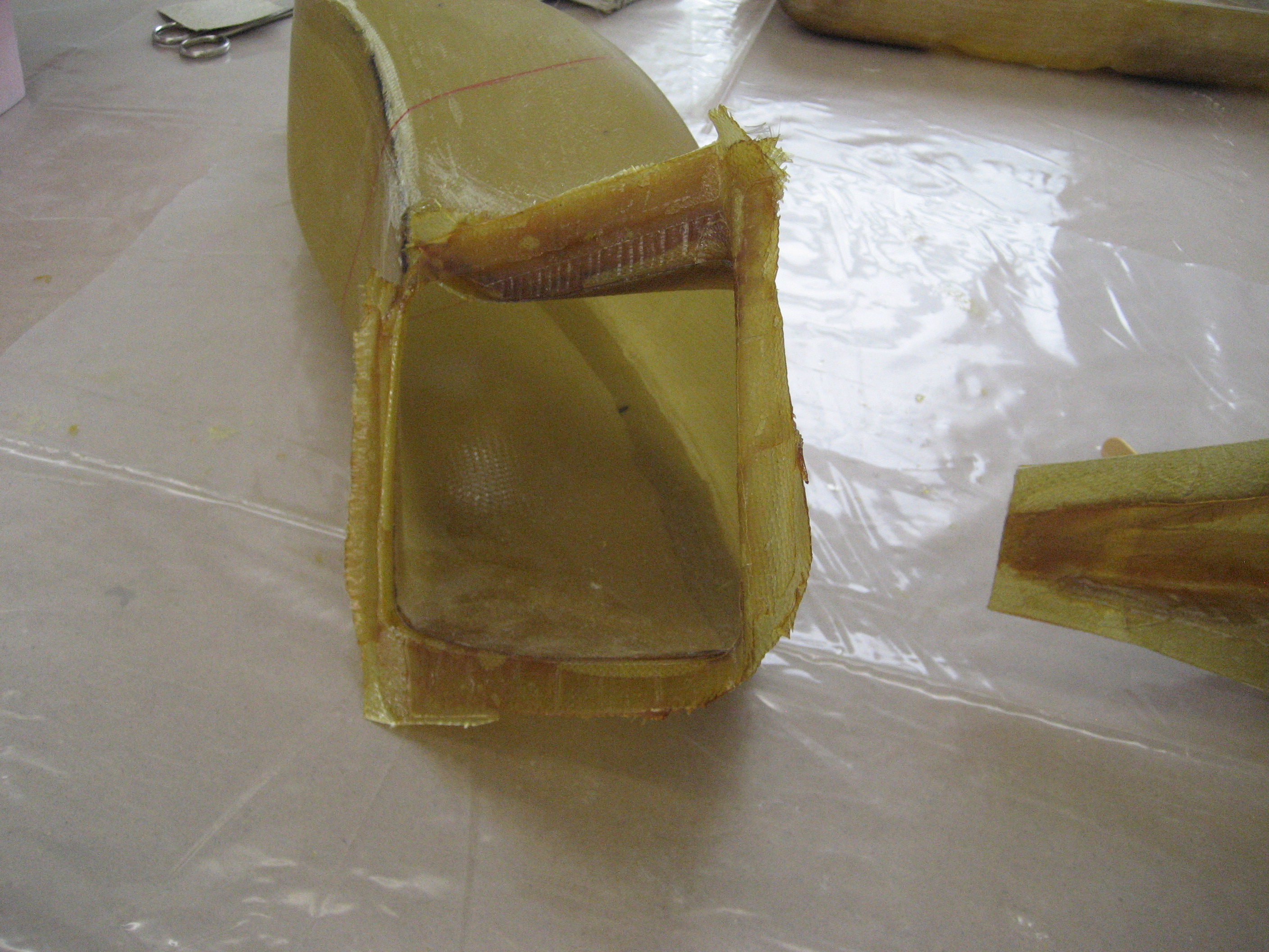
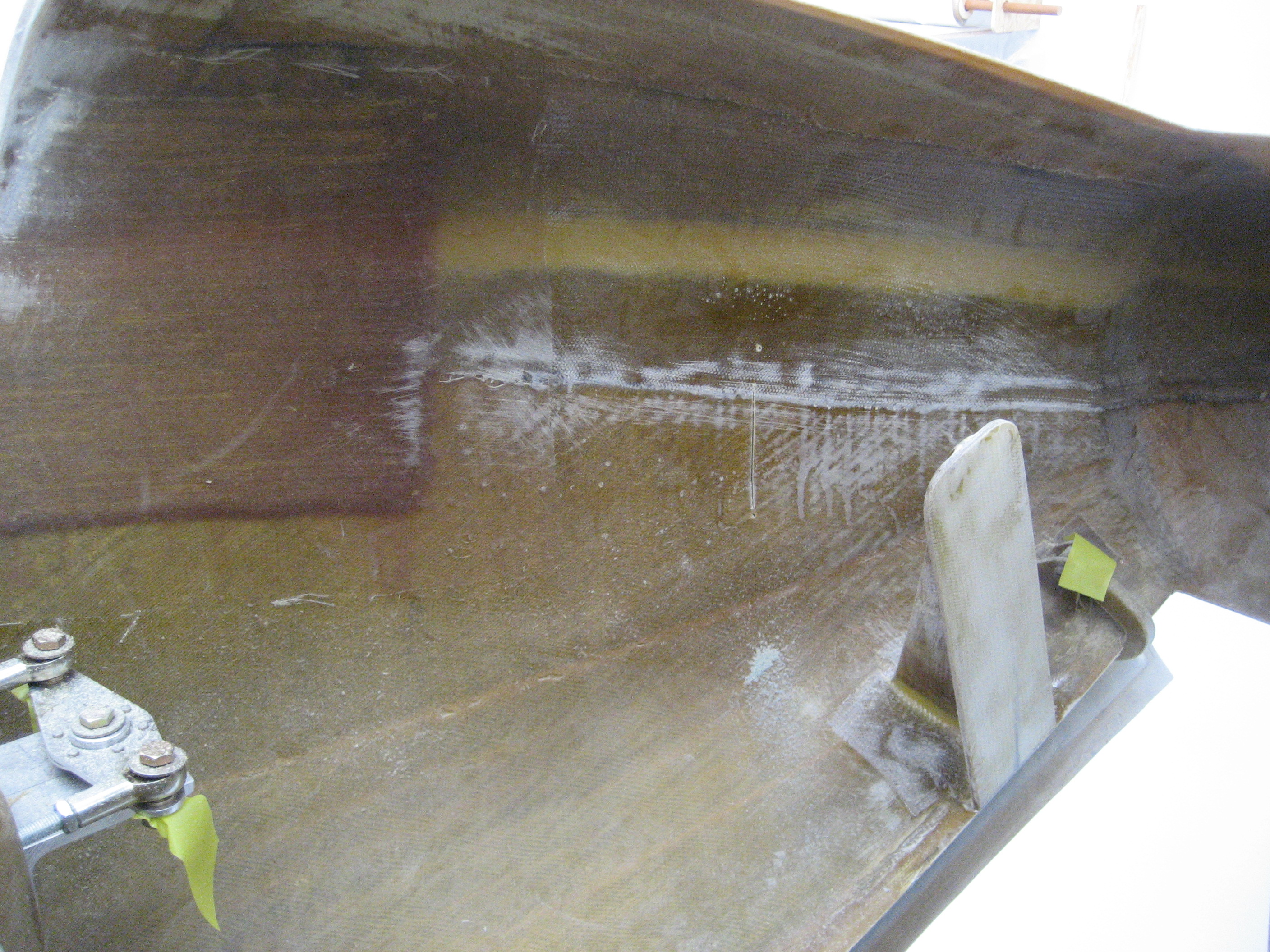
This is the duct for the air after it goes through the oil cooler. It directs the air out the bottom of the fuselage. I had to make a flange where the oil cooler mounts to it. Because the geometry of the design is different, I had to make a slight modification to the opening so it would cover the entire oil cooler.
Duct cleaned up with the flap that blocks outside air.
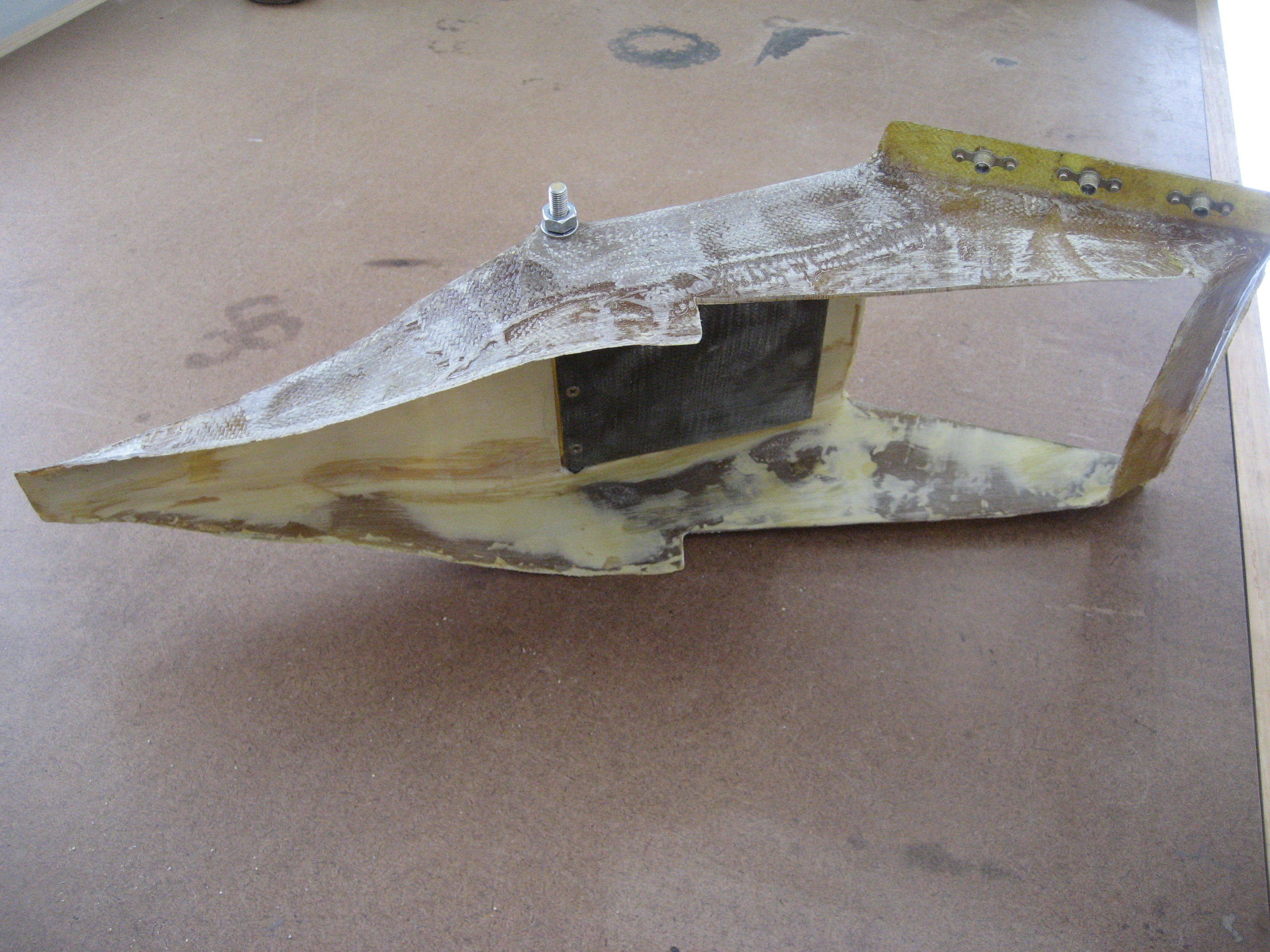
Flap open. You can see the inside return air port.

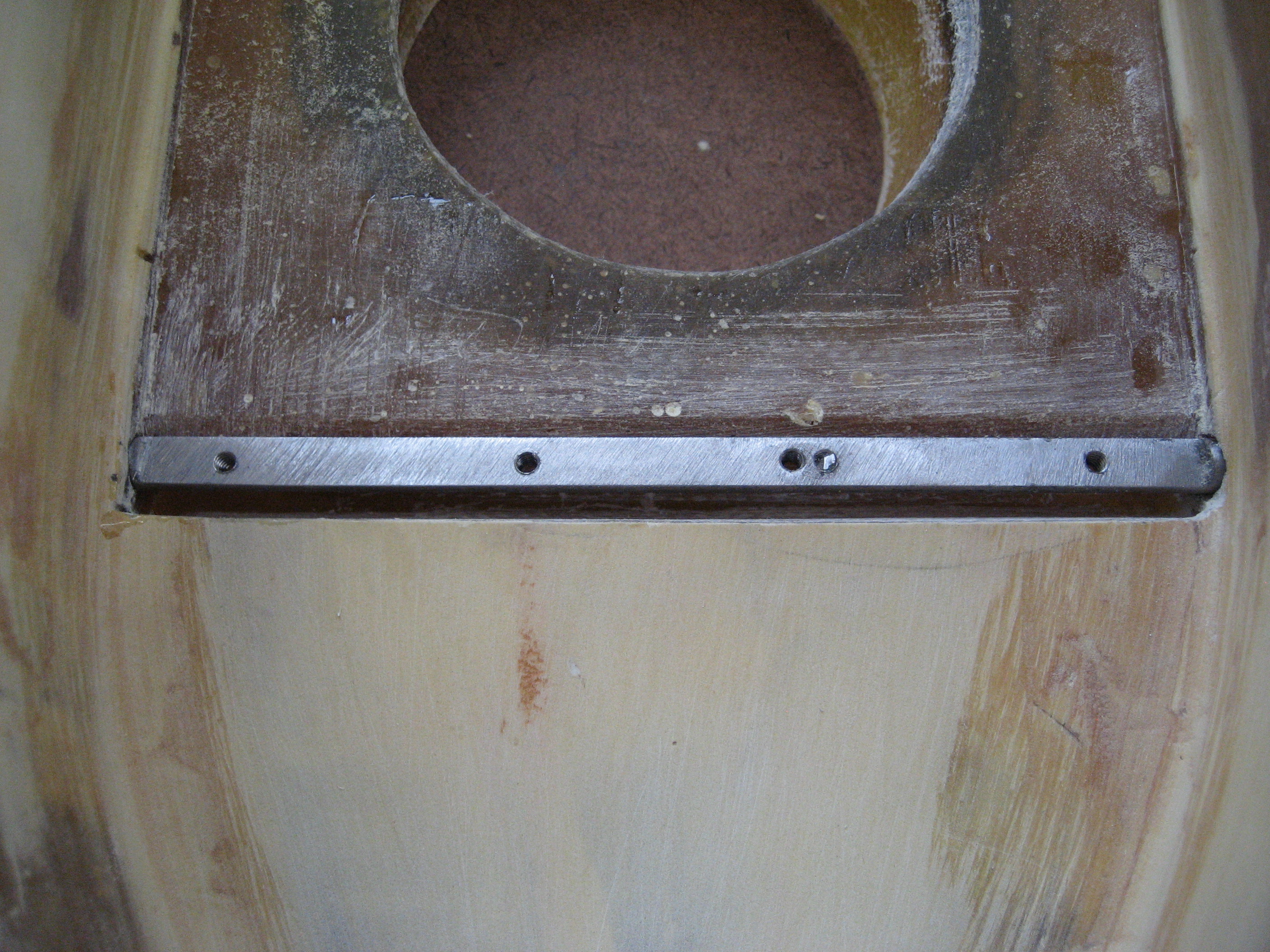
To make the pivot that the flap mounts to, I took a bolt and created a flat on the shank with a file. Then drilled and tapped the holes.
Here’s the mark for the opening
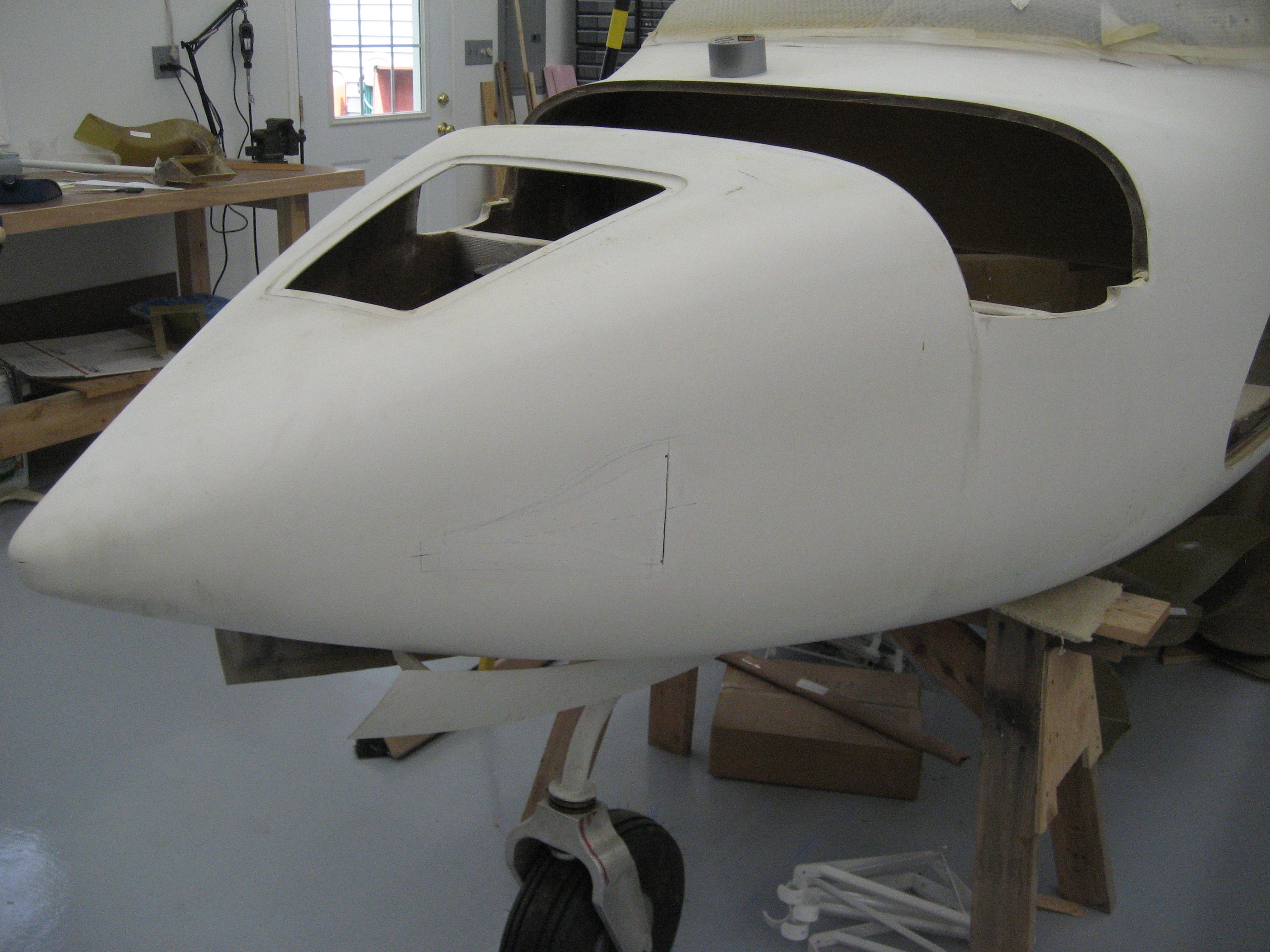
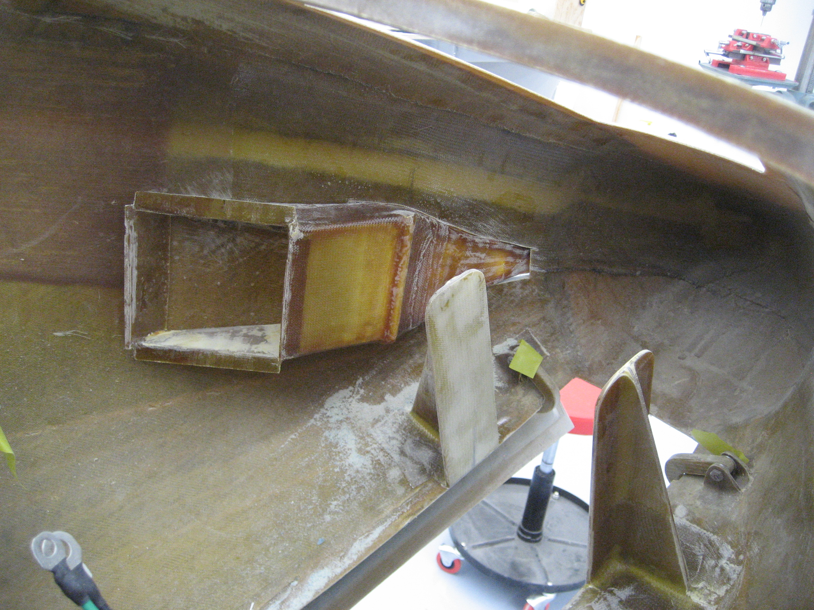
Inside view where the duct will go.
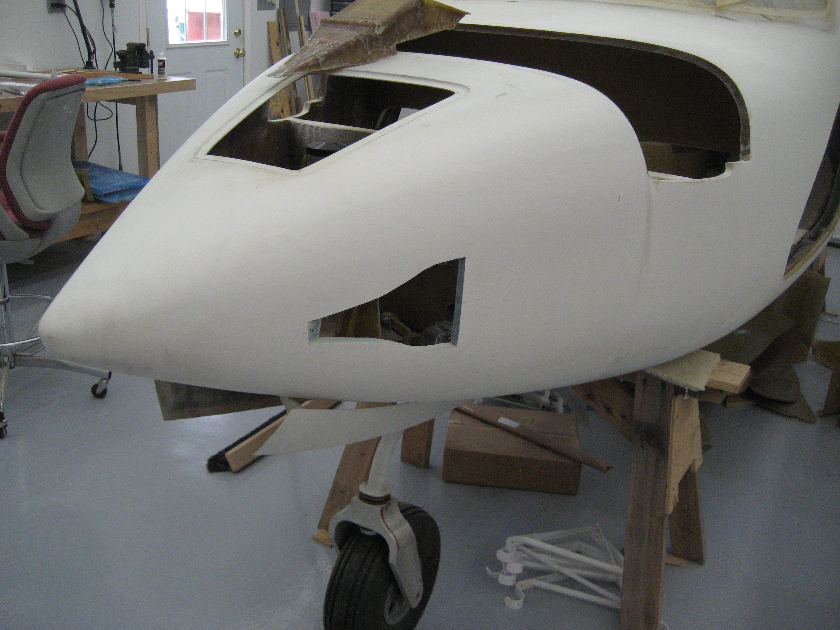
Now it’s time cut the opening for the NACA duct. This part always drives me nuts! I’m cutting a hole in the airplane! What if I cut it wrong? Oh well.
After the cut. Hope it’s in the right place.
Duct installed.

Inside view of the installed duct.

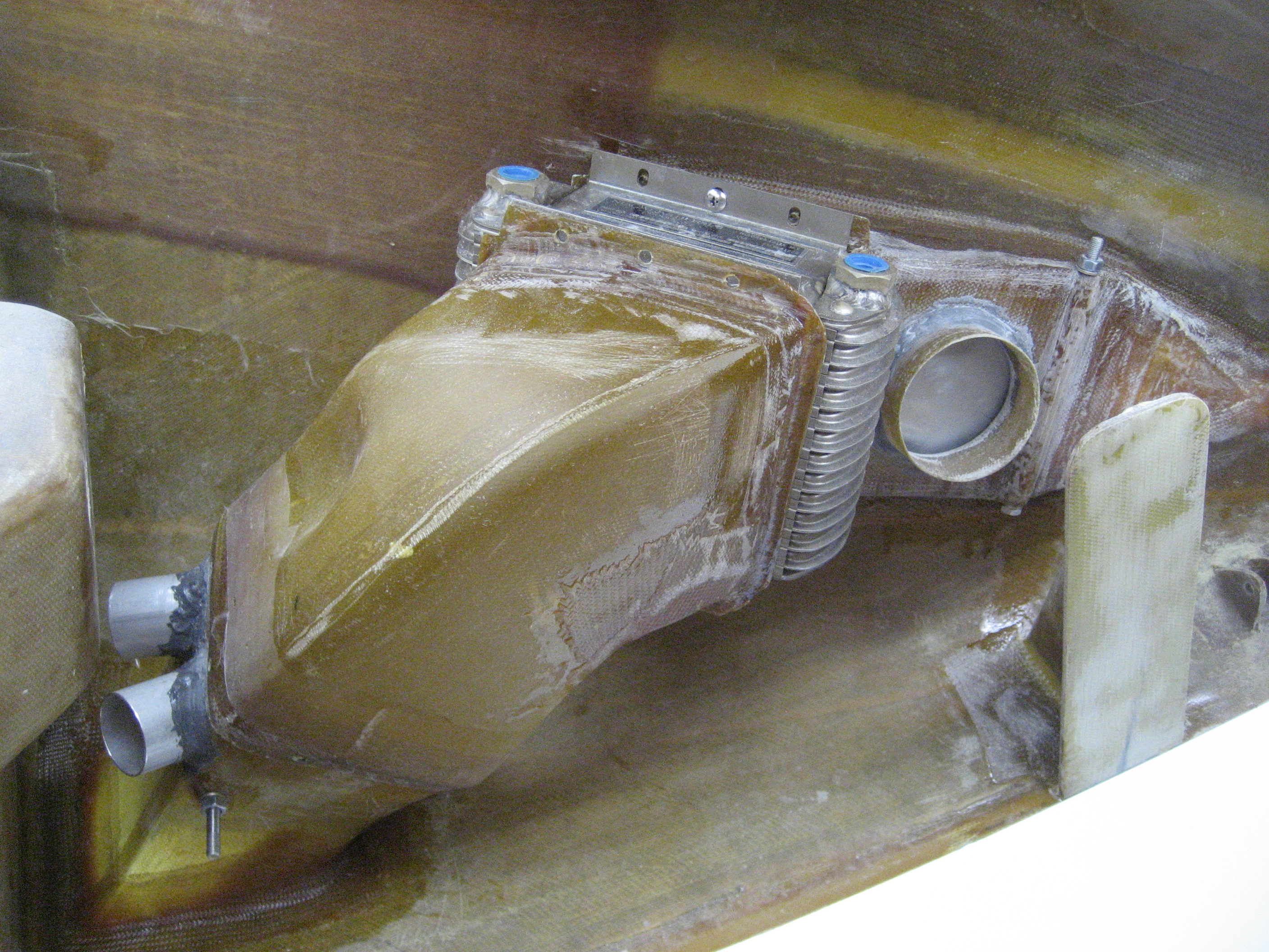
The whole assembly installed with oil cooler.
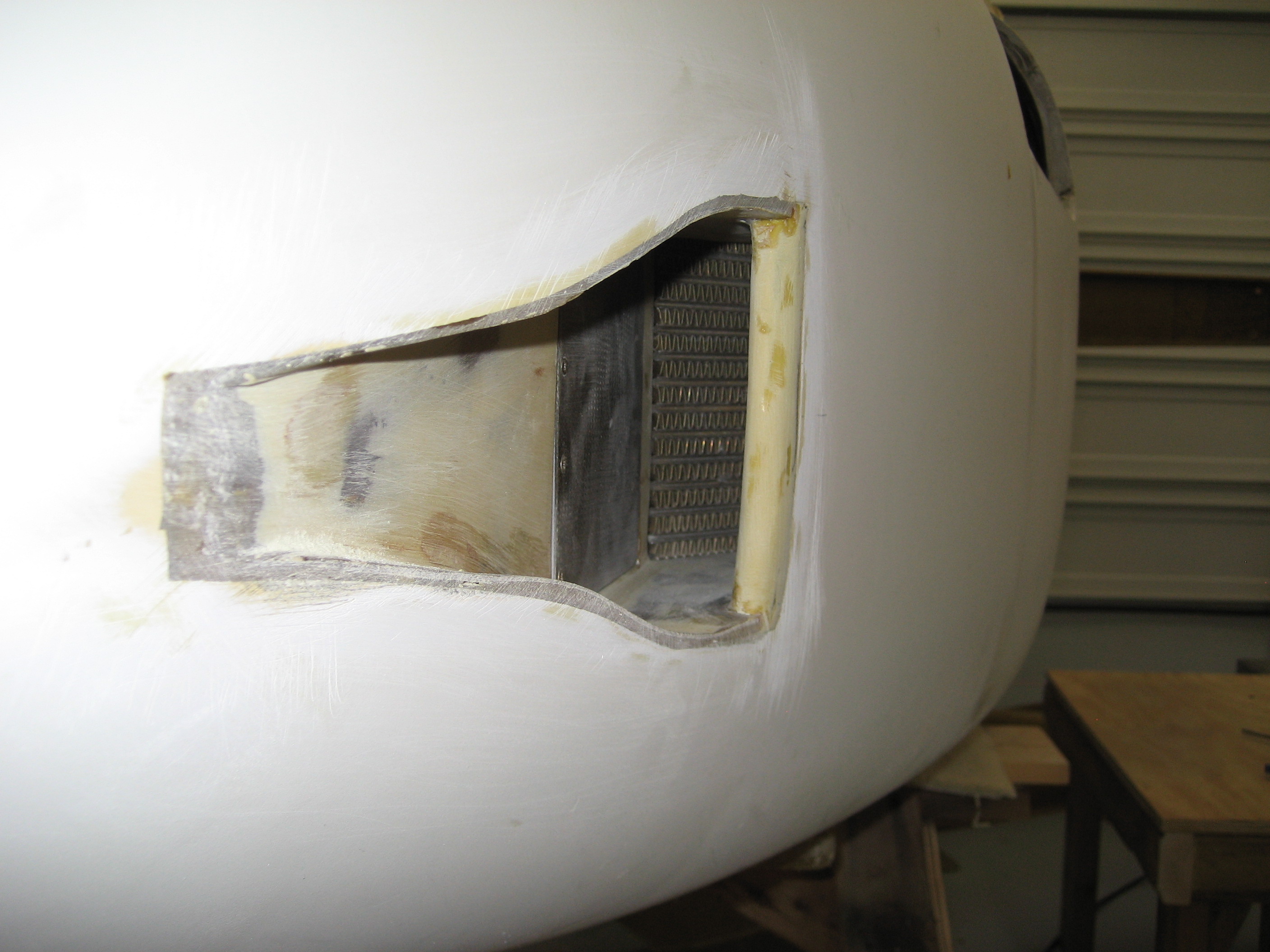
View from the outside. You can see the oil cooler inside.
Same view with the door closed block outside air from the cooler.

This is the lower air exit. I’ve installed the two 1-1/2″ tubes that will have flexible tubing connected to them which will go to the left and right side of the cabin. Here the flap is closed that will force warm air into the cabin.
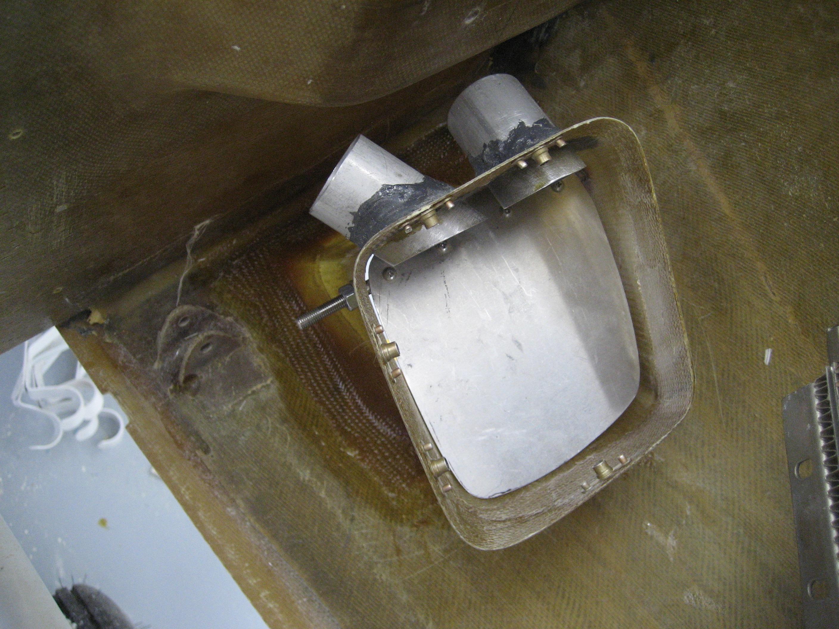
Same view with the flap open that blocks the cabin supply lines and exhausts the air outside.