
- 13.4.3 Pitot Tube Installation
- 13.4.2 Static Port
- 13.2.1 Instrument Panel Mounting
- 13.3.2 Ground Power Plug
- 13.0 Electrical System Documentation
- 13.0 Wire Labels
- 13.2.2 / 13.6.2 Aft wiring complete
- 13.8.1 Magnetometer connections
- 13.9.2 Autopilot Roll Servo Wire Routing Modification
- 13.7.1 Avionics Shelf
- 13.8.1 Magnetometer Mounting Bracket – Completed
- 13.8.1 Magentometer Bracket
- 13.1.6 Transponder Antenna Ground Plane
- 13.5.1 Navigation/Strobe Wing Root Connectors
- 13.0 Electrons are flowing
- 13.9.2 Autopilot Roll Servo Mounting
- 13.3.4 Overhead Switch Panel Wiring
- 13.2.2 Engine Wiring
- 13.6.2 Primary Alternator Connection
- 13.7.1 Avionics Shelf
- 13.8.1 OAT probe
- 13.2.2 EIS wiring
- 13.2 EFIS and Instrument Panel Layout
- 13.6 Ground Block – Part II
- 13.7.4 Headset jacks
- 13.3.4 Overhead Switch Panel
- 13.6 Ground blocks
- 13.8.2 Annunicator Panel
- 13.8.2 Annunicator Panel
- 13.8.2 Annunicator Panel
- 13.6 Electrical supply lines
- 13.6.3 Ground Power Receptacle
- 13.2 Instrument Panel Layout
- 13.3.5 Avionics Wiring
- 13.9.2 Auto Pilot Pitch Servo Mounting
- 13.7 Avionics and Wiring
- 13.7 Wiring
- 13.2 Panel painting
- 13.2 Panel installation
- 12.3.5 Minor setback on Avionics wiring
- 13.8.2 Annunciator Panel Problem
- 13.1.9 ELT Installation
- 13.6 Power Supply
- 13.7.4 It’s always something…
- 13.0 Wire routing
- 13.1.8 GPS Antenna Shelf
- 13.7.4 Audio Panel Relocation
- 13.0 Wire Routing (Remediation)
- 13.6.1 Battery Hold-Down
- 13.2.1 Instrument Panel – Final Install
- 13.3.3 / 13.5.3 Trim & Landing Light Test
- 13.8.1 EFIS alternate power
- 13.5.2 Cabin Lighting
- 13.1.4 Glideslope Antenna
- 13.3.4 Overhead Switch Panel
- 13.99 Instrument Panel overlays
- 13.99 Installing Engraved parts
- 13.99 Instrument Panel Lighting
- 13.4 Pitot/Static Remediation
- Static Port Conundrum
- GPS Replacement
- Secondary EFIS Power
- 13.99 Electrical System Diagram
- 13.99 – Current Sensor Repair
- 13.99 – ADS-B in antenna
- 13.99 – Switch panel update
- 13.4 – More Static Port Fun
UPDATE:
Well, that didn’t work very well.
Currently I’m back to my original design with some minor changes. The original static port was bonded in place. My new one is held in place with an AN bulkhead fitting nut. And instead of .75″ in diameter, it’s 1″ in diameter. I adjusted the height of the dam behind the opening and by doing low altitude passes over the runway at high and low speeds, I have got the altitude error down to about 10′. I still get the altitude “drop” when I rotate at takeoff, but the rest of the time, the error appears to be minor.
So I’m calling it done.
————————————
The other day during takeoff, I just happened to glance at the altimeter. Normally, the altimeter is not something you’re concerned with during the takeoff roll. But just before the wheels left the ground, I noticed that the altimeter was reading 50′ lower than the field elevation.
After reviewing the flight data for the past 30 or so flights, I discovered that the altimeter would go from the field elevation when the plane was stopped to 50′ – 60′ below at 70KIAS.
I thought that I had the static port error taken care of. But once I saw this, I did a constant altitude, increasing airspeed test. The GPS altitude should remain constant, but it didn’t.
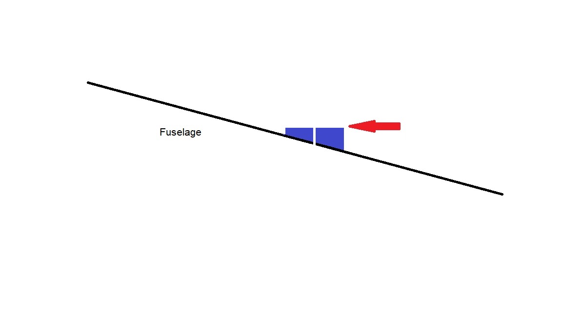
After thinking about it, I thought that the angle of the fuselage may be a factor. All the other planes that I’ve looked at have their static ports located where they are perpendicular to the airflow. In some cases where the fuselage tapers back towards the tail. But never at the front where the fuselage width is increasing. I think that’s because in that position, the static port could be subjected to ram air.

The location of the static port on a Velocity is where the fuselage tapers to the nose at a 15 degree angle. I think that the airflow may be affecting the pressure subjected to the port. Now it’s possible the boundary layer may factor in here but as I’m not a fluid dynamics guy, I really don’t know.
But here’s my idea. If I could match the angle of the static port to that of the airflow, I may be able to get a null pressure area.
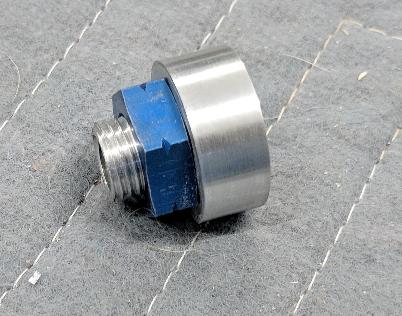
So I put some 1″ aluminum stock in the lathe and got to work. While I was at it, I decided to make another change. The current port is bonded in place. So changing it is a bit of a pain. The new static port will be held in place with a nut from a bulkhead AN fitting.
Here’s the new static port:
And here’s where is gets interesting:
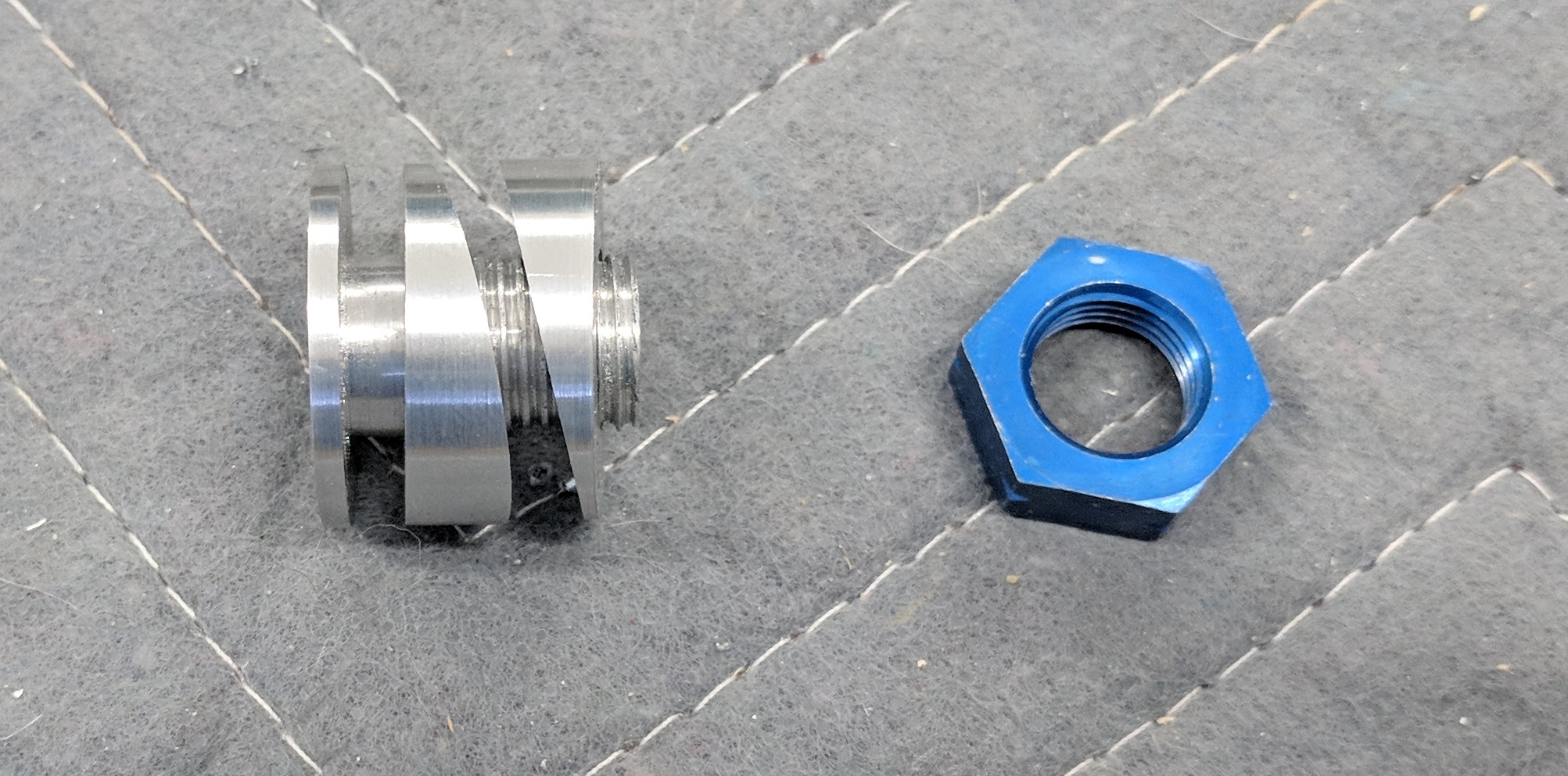
I have created 15 degree “wedges” that will allow the port to be perpendicular to the airflow.
I have absolutely no idea if it will work or not. After the baby hurricane makes landfall on Memorial Day and moves on, I’ll install it and find out.
Still can’t fly, but I got the static port installed.
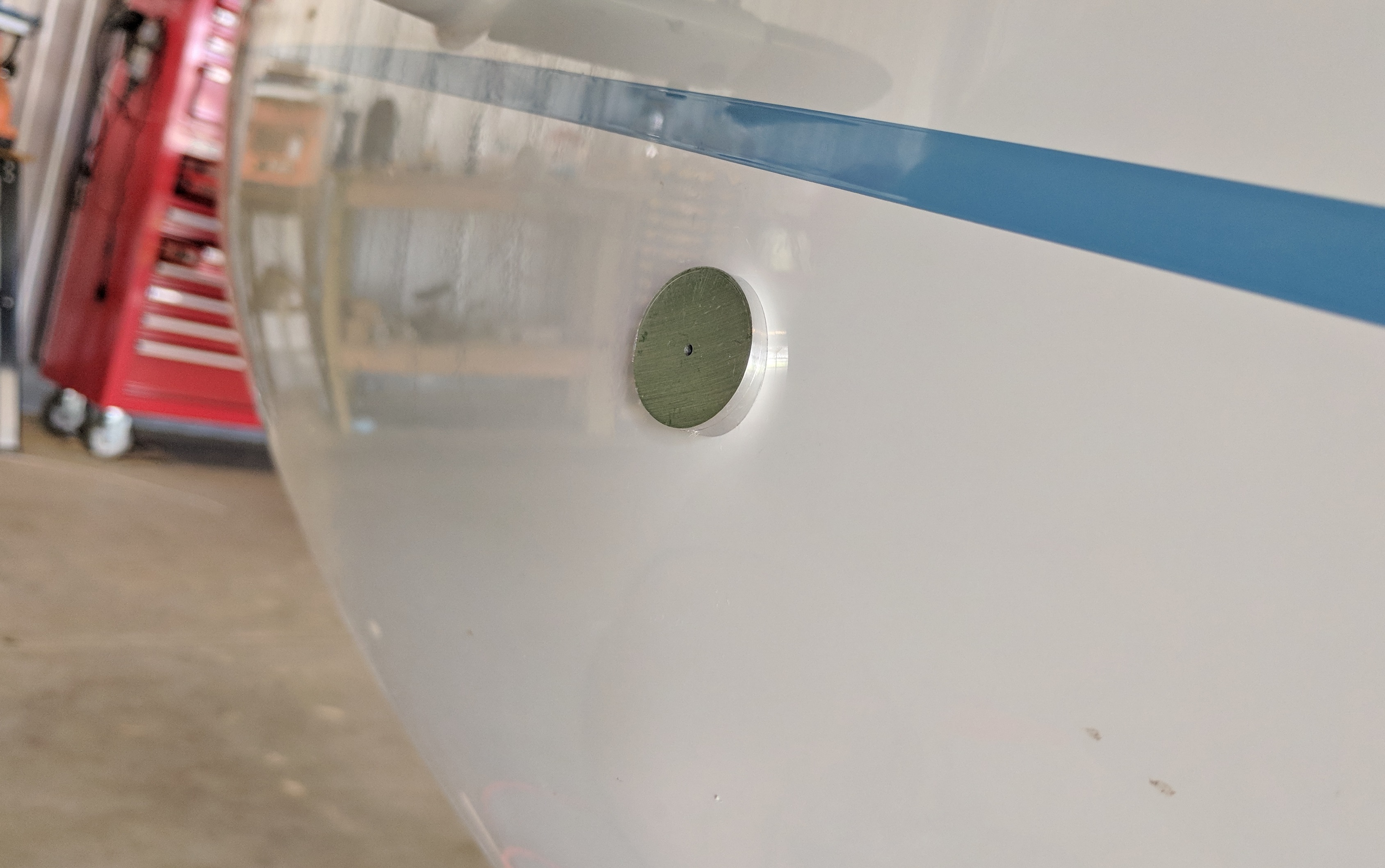

It is oriented to be plumb and aligned with the direction of flight.