
- 13.4.3 Pitot Tube Installation
- 13.4.2 Static Port
- 13.2.1 Instrument Panel Mounting
- 13.3.2 Ground Power Plug
- 13.0 Electrical System Documentation
- 13.0 Wire Labels
- 13.2.2 / 13.6.2 Aft wiring complete
- 13.8.1 Magnetometer connections
- 13.9.2 Autopilot Roll Servo Wire Routing Modification
- 13.7.1 Avionics Shelf
- 13.8.1 Magnetometer Mounting Bracket – Completed
- 13.8.1 Magentometer Bracket
- 13.1.6 Transponder Antenna Ground Plane
- 13.5.1 Navigation/Strobe Wing Root Connectors
- 13.0 Electrons are flowing
- 13.9.2 Autopilot Roll Servo Mounting
- 13.3.4 Overhead Switch Panel Wiring
- 13.2.2 Engine Wiring
- 13.6.2 Primary Alternator Connection
- 13.7.1 Avionics Shelf
- 13.8.1 OAT probe
- 13.2.2 EIS wiring
- 13.2 EFIS and Instrument Panel Layout
- 13.6 Ground Block – Part II
- 13.7.4 Headset jacks
- 13.3.4 Overhead Switch Panel
- 13.6 Ground blocks
- 13.8.2 Annunicator Panel
- 13.8.2 Annunicator Panel
- 13.8.2 Annunicator Panel
- 13.6 Electrical supply lines
- 13.6.3 Ground Power Receptacle
- 13.2 Instrument Panel Layout
- 13.3.5 Avionics Wiring
- 13.9.2 Auto Pilot Pitch Servo Mounting
- 13.7 Avionics and Wiring
- 13.7 Wiring
- 13.2 Panel painting
- 13.2 Panel installation
- 12.3.5 Minor setback on Avionics wiring
- 13.8.2 Annunciator Panel Problem
- 13.1.9 ELT Installation
- 13.6 Power Supply
- 13.7.4 It’s always something…
- 13.0 Wire routing
- 13.1.8 GPS Antenna Shelf
- 13.7.4 Audio Panel Relocation
- 13.0 Wire Routing (Remediation)
- 13.6.1 Battery Hold-Down
- 13.2.1 Instrument Panel – Final Install
- 13.3.3 / 13.5.3 Trim & Landing Light Test
- 13.8.1 EFIS alternate power
- 13.5.2 Cabin Lighting
- 13.1.4 Glideslope Antenna
- 13.3.4 Overhead Switch Panel
- 13.99 Instrument Panel overlays
- 13.99 Installing Engraved parts
- 13.99 Instrument Panel Lighting
- 13.4 Pitot/Static Remediation
- Static Port Conundrum
- GPS Replacement
- Secondary EFIS Power
- 13.99 Electrical System Diagram
- 13.99 – Current Sensor Repair
- 13.99 – ADS-B in antenna
- 13.99 – Switch panel update
- 13.4 – More Static Port Fun
While waiting for the paint (yeah, yeah, yeah. Primer) to fully cure, I build the glideslope antenna. I used the RST Engineering foil and placed it between the bottom of the windshield and the doghouse opening.
Here’s the two pieces of foil that will be the two legs of the antenna.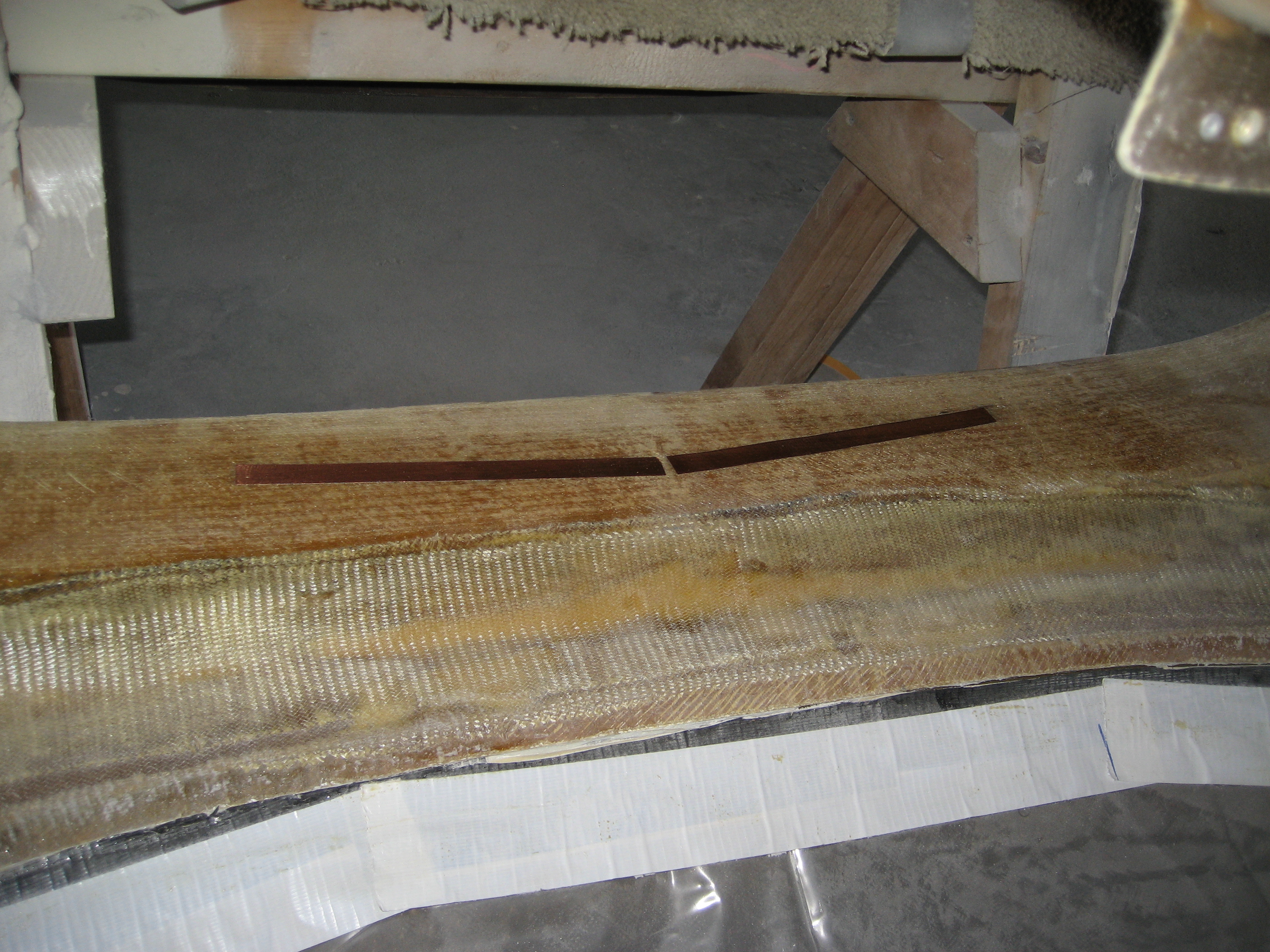
And after the coaxial leads are attached and then covered with thickened epoxy and then a layer of BID.


Sadly, I would later learn this was a TOTAL waste of time. The Nav radio that I purchased didn’t have an input for the glideslope antenna. When I asked the manufacture, they told me that they get the signal from the VOR antenna and that almost nobody uses separate glideslope antennas anymore.